CNC CODING GUIDE Website
Free NX 7.5 - NX 11 training book, self learning instruction
This is a complete course from the beginning to the making of your first sketch, model and finally a nice manufacturing with a ready-to-use CNC program
You going to accomplish both sketch, model and manufacturing
-12 dec -18. I'v started the process to correct the written language, bits and pieces of it are ugly thanks to auto translate
If you feel to pay any amount of money to me for the work with this use this link paypal link
Create new file
We start all with
creating a model
Go to File >
New or use the icon with the same name.
choose the Model
tab, make sure Millimeter or Inch is selected for your desire
NX does not
handle file names, directory names, and more very well. It is important
to "format" the name correctly. Do not use Åäö and%-like characters.
Spaces shall be
represented by _ (underscore), the same applies if you mix numbers and letters.
The default directory
does not work good at all, creating a directory called CADCAM on your C drive
(c:/CADCAM) is the best choice
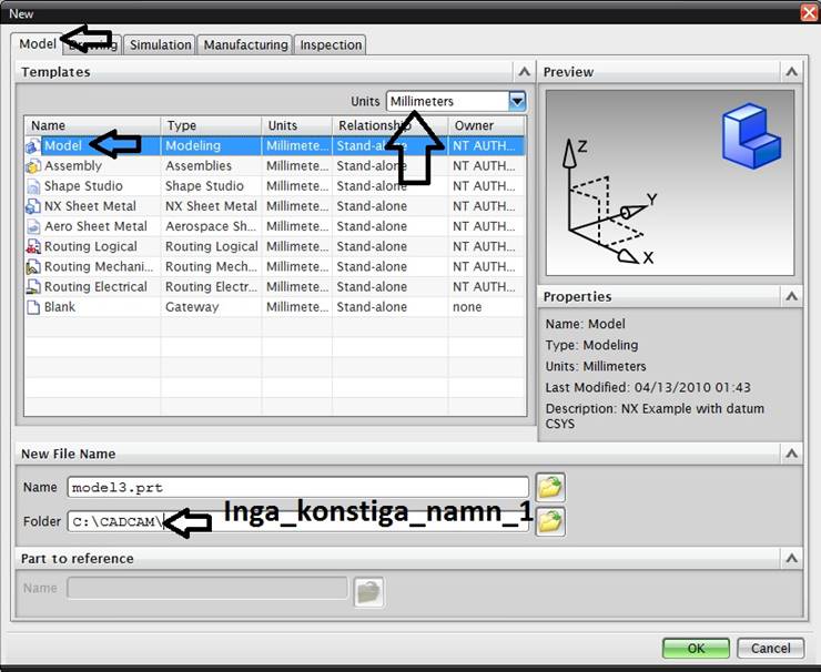
Text on pic = No funny names
Create
sketch
A solid is an
"air tight" form, we create the base of this form in 2-dimensional mode to create the air tight
volume on this later
To get the X, Y
and Z coordinates right from the start you have to follow a special pattern
when drawing in Sketch mode. Missed this now, it will give you problems towards the
end. Take note of the X,Y and Z-directions, really a p.i.t.a. to change later
Click the Sketch icon at the bottom (arrow) Make sure that Inferred option is active in plane method, Drag the pointer over the drawing area so the square lights up around the arrows, don't click! Select OK
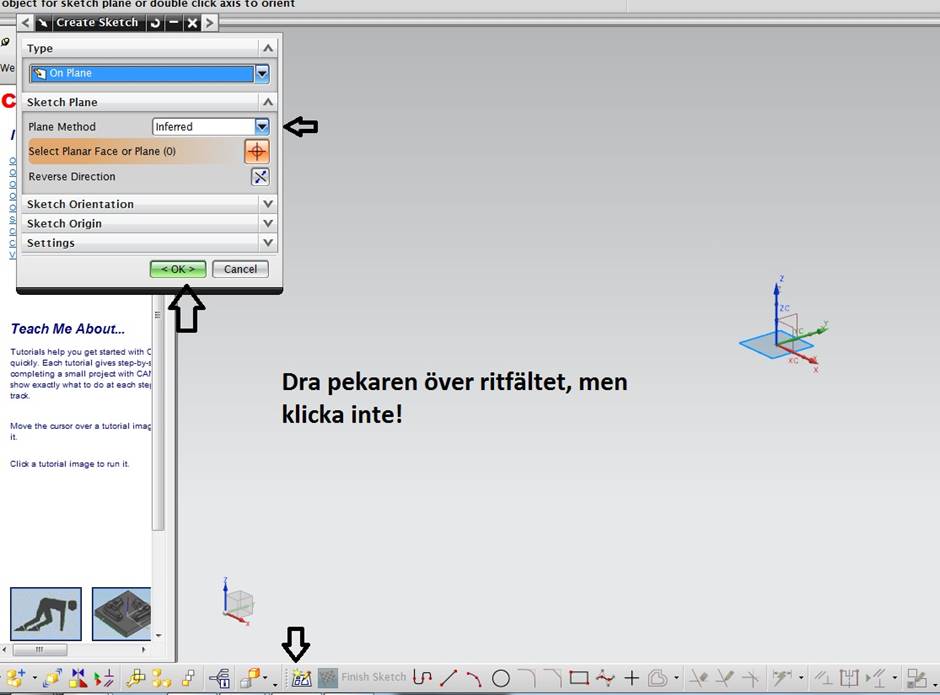
Text on pic
= Hold the pointer over the sketch area, but do not click
Draw the
figure
All the details
we will make are based on squares and circles.
Turn up the CSYS
(as that 3 pointed Arrow shape is called) so that you have Y up and X to the right, Z
should point you straight to your nose
Choose to draw a square
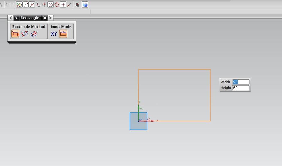
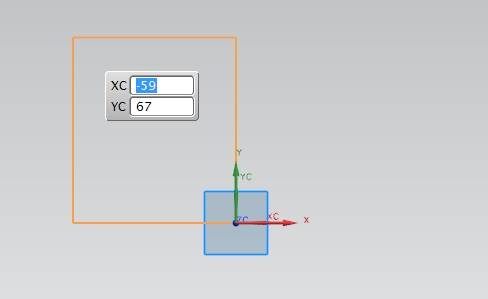
Make sure to be
in the position with a square of 2 digits in the top left, dimensions are
entered and you have the option WIDHT Height or X and y, x and Y options keep
track of whether you are on the minus or the plus side of the figure. In W and
H mode, you must be in the correct quadrant with the pointer. See figure below
Type 0.0 to set
zero, then type the dimensions for the size of the square, right-click and choose
OK
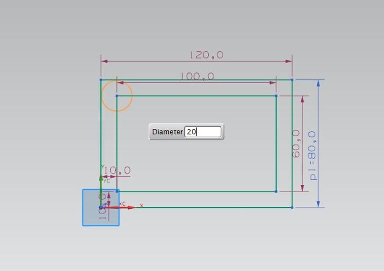
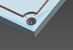
After as we
previously clarified that everything is circles and squares is a negative
radius only part of a circle, select the Circle function and click on the inner
square corners. Make hole Ø to Ø20 (RADIUS 10). Click on the other three
corners without exiting the command
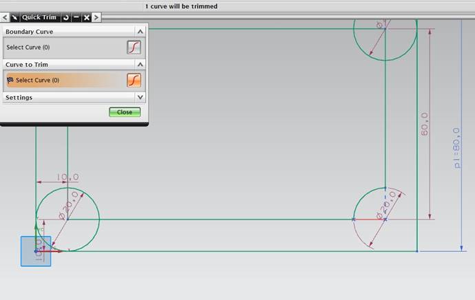
We need to trim
down the circle and a small part of the square so that it becomes a negative
radius.
Select Quick
Trim. Click the lines you want to remove.
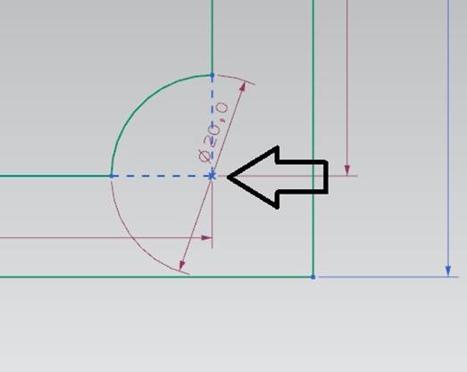
Center-Marking or point
for hole-extrusion needed.In many cases a mark in the centre of the holes
with a + (point) in order to be able to select them when creating holes later. In this
case, it is not necessary for the centre points to be created by previous
drawing parts
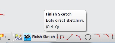
Select Finish
Sketch to enter 3d mode
Create a
solid model
Select the Finish
Sketch to get over in the position where we can create a solid of our stretch.
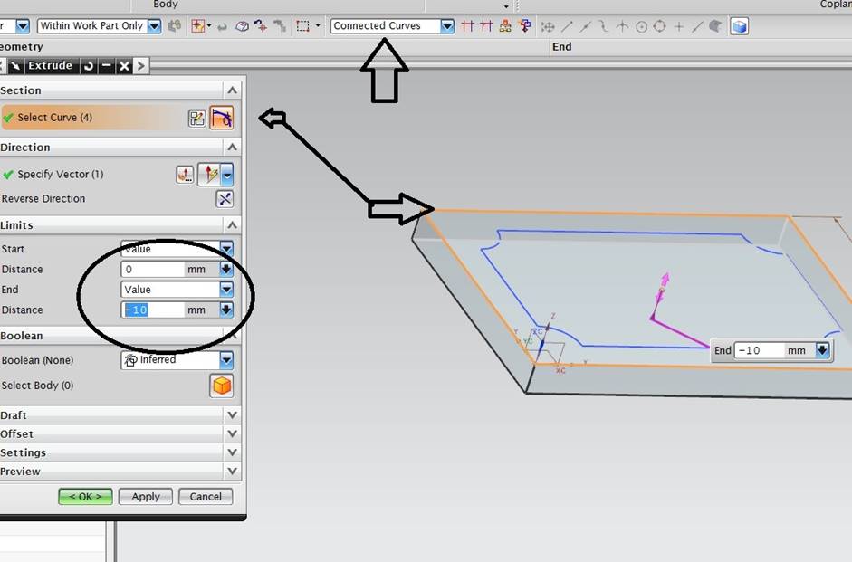
The first
extrusion is the outer square. Select Extrude and double on one of the outer
lines, notice that connected curves must be selected. If the O-selected is
selected all the Infered is used.
Extrude in Minus
so that you as long as you can keep the drawn lines on the model top.
You can also pull
out the extrusion if you pull the purple arrow
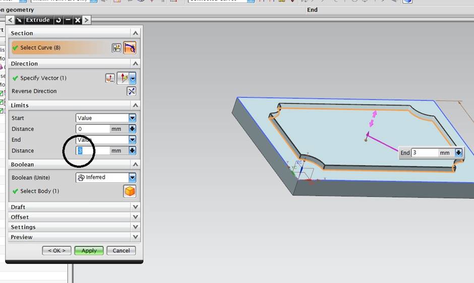
Extrude up the
top as you extruded down the bottom part
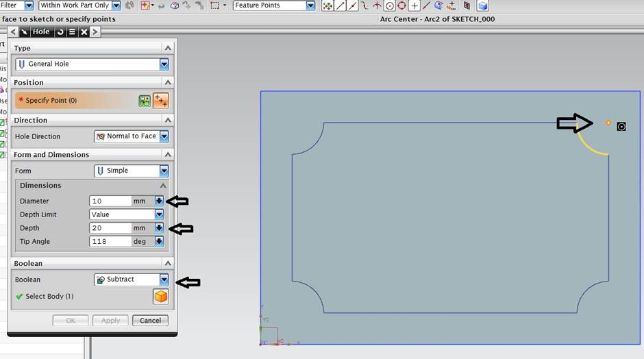
The holes are
extruded with command Hole. Point in the box is the point to represent the hole
center.
Enter diameter 10
Depth limit can
be through Body, thus consistently or as in the box below, as Value. It does
not make the hole too long, as the hole that does not contain anything is
outside the piece
Create a
manufacturing
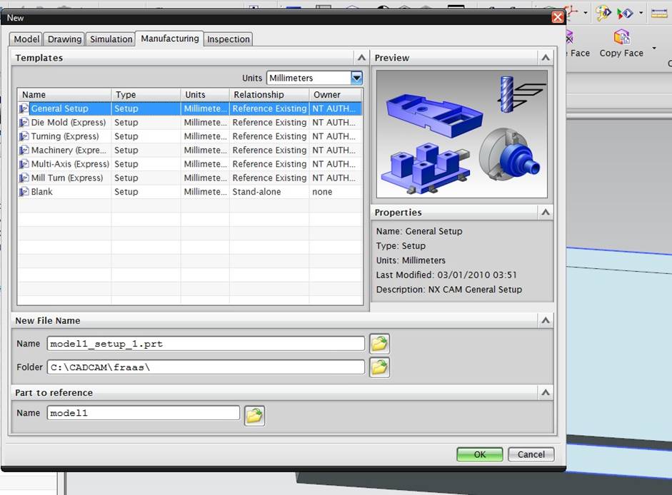
Select File >
New from the top menu. Select the Maufacturing tab and select General Setup. Make
sure the units are in millimeters or inch
The name of the manufacturing will be your Modelnamn + _ setup_1. Prt, folder shall be in accordance with the naming conventions of NX. Part To reference is your model.
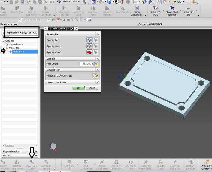
You should be in
the operations Navigator mode and in Geometry View
We need to tell
the NX which your model you want to use and create a Blank, which will
represent your workpiece before milling before processing.
Double-click
Workpiece
Start by
selecting Specify Part
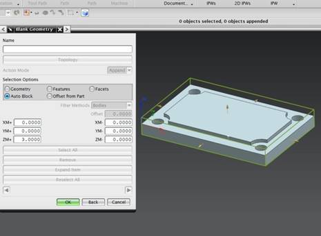
Blank Geometry
Choose as Auto Block, then the size represents the model's extreme values. You
can enlarge the Blank so that it provides processing on top and sides, but in
this case, we allow all values to be zero
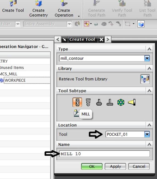
In this General
Setup there are no default tools. So we must create them from new.
Click Create Tool
Type should be
mill_contour, Tool subtype containing different tool options, select Mill which
is a regular endmill
In Location
Select tool switches the location
Call the tool for
something you recognize, but remember how things get called according to NX.
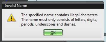
Since I
deliberately made a mistake in this operation, we get an error message. I do
not reveal the error, it allows you to easily figure out yourself (NX 11 will handle spaces, 7.5 not at all)
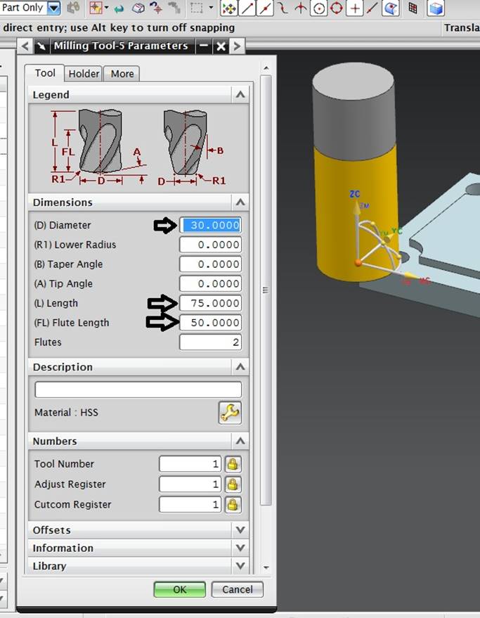
We have to put a
number of values on the tool, diameter is most important.
Length is the
total length of the endmill, Flute Lenght is the length of the flutes, what is
shown yellow on the tool
Create
Operation
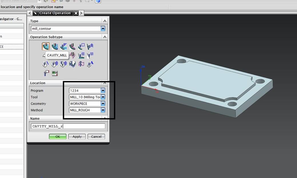
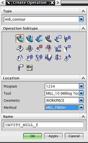
We use
Mill_Contoure as the Type
Operations
subtype contains lots of different processing options for processing, you can
use for example Z_level_profiling if you want to drive around the outer edge of
a detail.
We use
Cavity_mill quite often when it clear a number of different machinations.
Program 1234 does
not need to be changed
Tool, choose your
suitable tool
Geometry:
WORKPICE (and nothing else!)
Method adapts to
how you intend to process, options Finish and Rough
Names can be
changed to something you recognize, think of the NX and its naming rules.
Make sure the
WORKPIECE is your Geometry
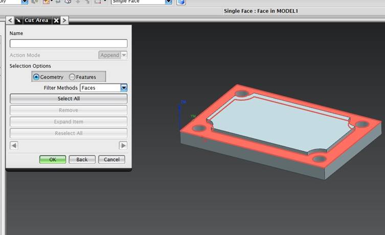
Click Specify Cut Area
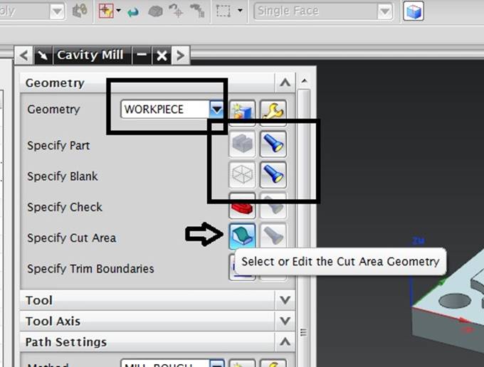
Select the area
you want to process. Sometimes you also have to choose the edges, but not now.
Go at the bottom
of the box and generate your choice, NX calculates the tool path now
If you change
something in the operation, you must regenerate
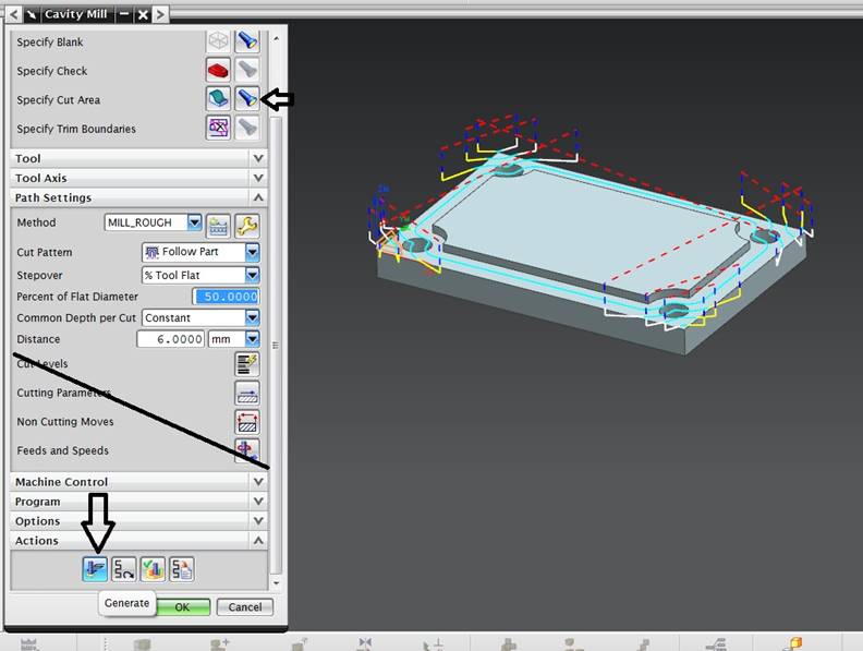
The generation creates the tool path, which includes quick runs and machinations, quick feed is red and blue, light blue is cuttin in the material. White and yellow represents approach and departure.
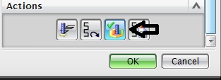
Verification
shows how the tool processes in the blank
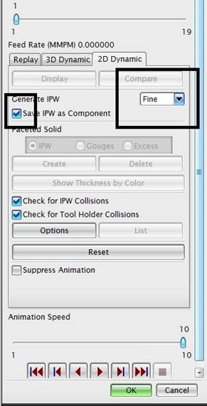
But it also
creates the new model that will be after you have worked away, this used the
nice run then to know where the material is already gone and you do not have to
drive again. Then we have to choose to create a IPW (in process workpiece)
Create
Mill_finish
The operation is
basically the same as rough driving except that Method MILL_FINISH.
In this operation
the same as the rough run.
Select surface
and generate. Don't forget to save on ![]()
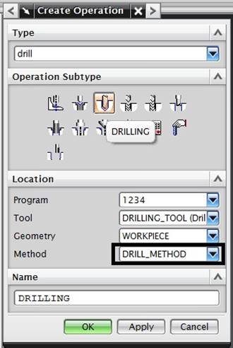
Create Drill operation
(Not in NX 11)
Select Drilling,
drill that you created and Method Drill_method, even here you can call the
operation for any name.
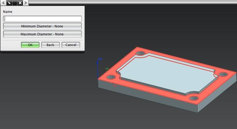
We skip the next
phase, which is the choice of diameter, we have gone through in the choice of
Mill and it looks alike here
In drilling we
have 3 choses.
Select holes can
be done by selecting > All holes On Face and selecting Top surface. If you
have more different large holes you can delimit the diameters before clicking
the surface
Specify Top
Surface selection is also Top surface, but it should be chosen as plane
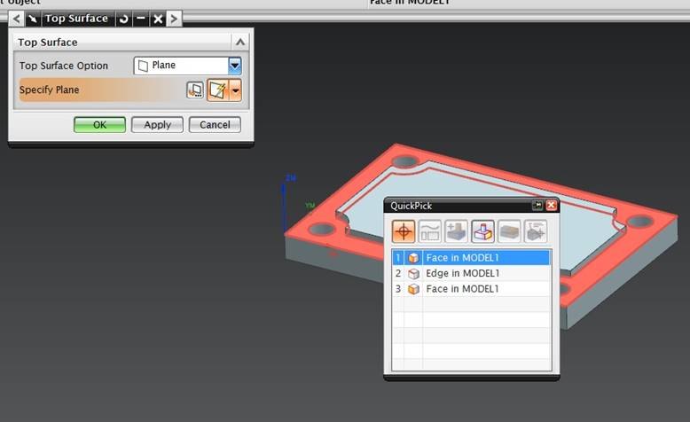
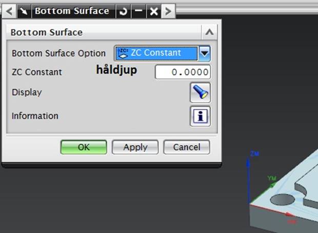
The bottom
surface choose either the plane and the bottom surface or the drill depth with
ZC Constant, this does not require any click on surfaces
Generate the
drilling and study the tool path. Check carefully that the drilling really goes
down the hole, it does not do it, you have done something wrong in your model
or tool choise.
Red path
represents the coarse feed (G00) light blue corresponds to the working feed
(G01), when the colors are mixed, it is both types, in this case G01 down the
hole and G00 up out of the hole
Now all share
ready, it's time to verify the entire run as a package.
Select Workpiece
in Operation Navigator on the left, right-click, select Toolpath > Verify
Would! be
replaced with a stop sign, right click on the Workpiece and select Generate in
the menu, OK on all questions
Post Process
Now everything
should be adapted for a CNC machine.
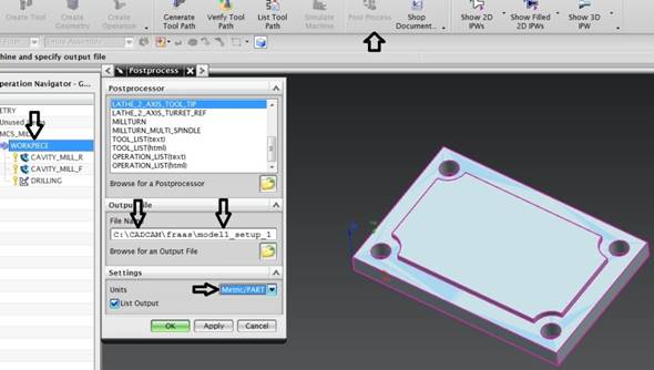
Stand on the
Workpiece, click the post Process, either on the icon menu or with right
Select
Mill_3_Axis as the post processor (or the assigned to you)
In the File Name
box you should have the names right, otherwise this does not work at all, you
can not post if you have not followed the rules of name making.
Also choose
millimeters in the units as when needed, in this post, the Americans have poked
in both inchs and feet in NX, we don't want to use that if we are metric guys, our parts become 25.4 times smaller
.
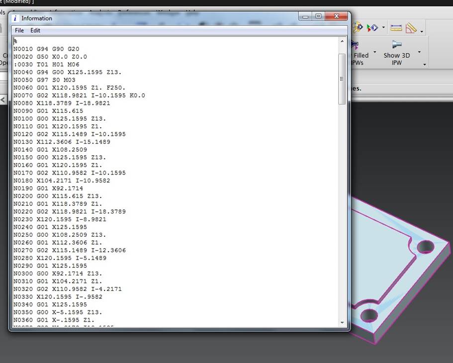
You get the code
in the format we ordered, it is almost ready.
You need to
change some things, including the tool change rows that have the introduction: 0030 and
so on, this is necessary to do before we even try to bring anything to the
machine.
The one with good
memory knows that the sign:(serial file transfer between computer and machine, : is the program name) Indicates the program name that the machine will
assume, so you have 5 tool changes, the machine divides your program into 6
parts, completely unusable in other words
Threading
with Tap
Create a tap in
the Create Tool as usual, Diameter, Pitch and save this.
Select Create
operation, drilling and tapping operation
Select holes
according to drilling on Cycle – Standard thread
-Select OK at
Number of Sets
-click Depth,
select Bottom Surface or Model Depth for continuous threading. You can also set
the depth with the option Tool Tip Depth, then you get to enter the thread
length
-OK, OK and
generate
Threading
with Thread mill
Thread milling
works both with thread made in solid and with a straight hole, but unlike lathe
threading, the cutter operation does not inherit the properties from solid
thread.
-Create tools
-Create Operation
– Mill Planar-Thread Milling
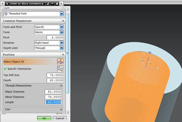
-Specify Hole or
Boss button
Change From And
Pitch to Specify, mark the mantle area in the hole
Form shall be
Metric
Pitch is your
ascent (which is the same here and on the tool)
-Threading drill
Size same as thread inner diameter or drill diameter
-Depth must
correspond to thread depth
Also
-Major Diameter
(thread YD)
-Minor diameter
(drill Diameter again) (Dia-Pitch)
-Lenght Same as
thread length
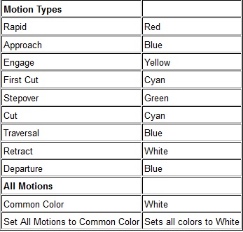
Identification
of feed types
In order to be
able to identify what the processing does after generation, among other things
to find faults, all feed types have a pre-selected color, for example where
tools cut into materials become the tools light blue, quick feed becomes another another color depending on departure or approach.
The table below
shows the appropriate types.