Controls of the Millplus IT
Video showing the functions in millplus
This is a beta test, need lots of editing
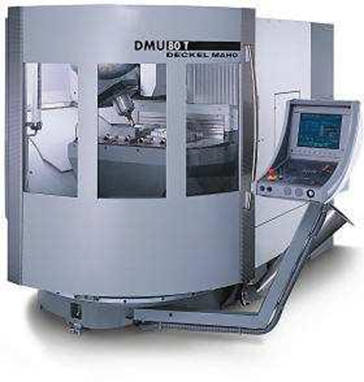
The machine
controller is MILLPLUS V500/510
The machine is
fully ISO/DIN based
There is a
simulator to download to this control system
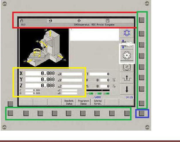
Screen Layout
Red field:
Modes of operation
Yellow field:
Axis values on the left, residual to
Right
Green field:
Function buttons with dependency
On
operating mode
White field:
Tool Changer Mechanism
Blue bar:
Information button to display alarm and so on
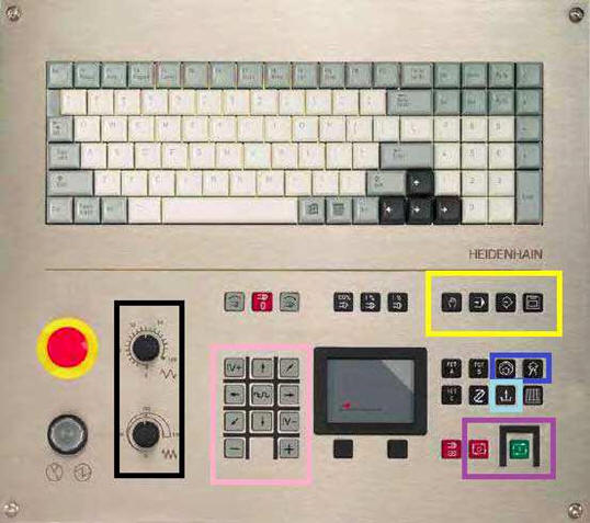
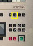
Keyboard
Yellow field
:
Selecting the operating modes
Blue Bar
: Cooling
Water
Purple fields
:
Program Start/Stop
Black Field
:
Top control fast feed, bottom control Work Feed
Pink Field
:
Manual Shaft Movement
Light blue Bar
:
Open Door
Keyboard is
used for text input and to introduce
values to the control
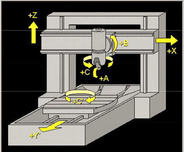
Machine axes and movement
As usual, X Y and Z are just like on any other machine, however, there are two
new axes, B and C.
B is the rotary milling axis of the mill head, values from B-32 to B1. 5 (With
M57, -90 deg)
C is rotary milling axis of the table 0-360 degrees
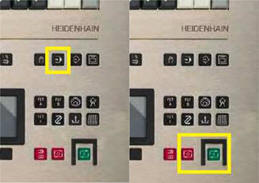
Start the machine
Main
switch on
Release
the Emergency Stop switch
Press
(Hold button), and CLEAR (F10)
Before
you can use the machine, the reference point must be run

Select the
button below, make sure the door is closed, the machine
announces closed door with a small beep

The button text
is in swedish but I think you got the message
Run the Cycle
Start button (the green one)
Manual operation of Machine axes
All axes can be
manually run in MDI mode.
The different
axis drawings are shown below
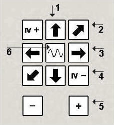
|
1. Z-axle |
2 |
Y-axle |
|
3 X-axle |
4 Axle 4 |
|
|
5 Axle 5 |
6 |
S Rapid feed |
Programming
Select Edit
with the menu button
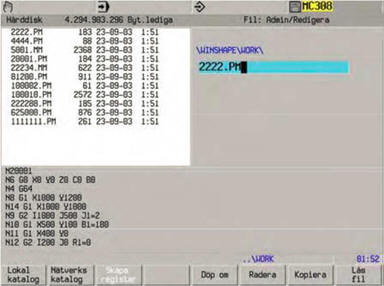
In the folder
tree, select Folders.
New program:
Enter number. PM to load a new program
Open
existing: Select applications and press ENTER on the Keyboard
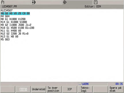
Program in ISO
Code
The first line
shall be the program number starting with N
The control
keeps track of codes for You
If you want to
know the usual M and G codes the system uses, press the (I) button
The whole line
you edit is blue marked, but in the blue marked there is a _ that show where you
type
Programing exemple
Programming exemple with explanations
N111 (program name
N1 G17 Choice
of PLAN)
N2 G54 I90 (Zero
point, I is the index)
N3 T12 M6
N4 S1500 M3
N5 M7 (int cooling)
N4 G0 X20 Y40 Z60
N5 G1 Z50
N6 G0 Z100
N8 M30
The machine
does not allow two M-codes and G-codes in the same block
axis of rotation of the table is called C and programmed in, for example, C180,
C0 is always at exactly the same point
Shaft for turning the cutter head is called B and can be angled 35deg as
standard in one direction and 1.5 degrees in the other. Example B-35
But if you use M57 you can turn the mill head to -90deg
There are a large number of special G-codes that can be used for various
features of the run, however, there are so many, G stretch up to G700-someting,
please read the manual (700 pages) There is also a programming support that help
helps you create Runs, check out the Programming manual for that information (I
can give you a copy)
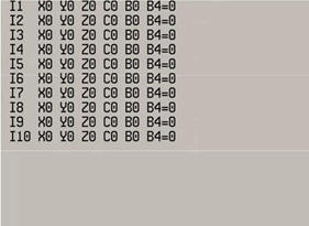
Zero-point setting
The zero-point table, G54, has lots of valuse according to the table zero
points. These are denoted by I (ex G54 I5)
Set your own
zero point
:
Start by typing
G54 Ix in (the number you want to use)
In MDI
and press run to select G54
After that,
select the Zeropoint button that is available when you press the drive Mode
button.
Then you stand
in the position that is O and
Zero there by
putting values in the axis fields
Push

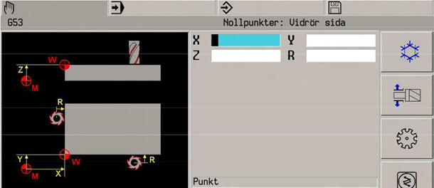
Touch the workpiece with a tool
do add the radius before NPF
Zero point register have values for both B and C axis
Running the program
Choose the run mode
Choose your program in the file manager
Programmet is ready to go
Press Cycle start (yellow)
Note that you got two feed rate knobs, the upper for rapid and the lower for
working feed
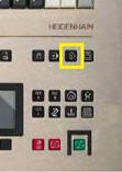
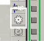
Tool change
Moving the control panel to the left side of the machine behind a transparent
door are the tools.
Rotate the
right tool with the button in the picture, you get the choice over which
direction you want to rotate and which switches the discs you intend to use
The tool that can be replaced is what sits in the middle of the opening on the
corresponding tool changer disc.
The tool is
gently broken away from the bracket.
The new tool
should be inserted with the Capto track towards the LED!
Click Run
mode and the Tool button You must specify the approximate radius and make
sure the
E-number is not 1 or-1, that parameter should be left unfilled or zero.
G-code for tool-measuring with laser
G601: tool length
G602: tool length and dia
Tool length and dia
Before you use the laser to measure a tool you need to pre-config the tool, add tool radius (R10), the approx tool legnht (L100),amounts of flutes or cutting edges (Q4=4) M3 0or M4 (I2=0)
Addresses from the tool register
Following tool
values can be used:
L=Length
L4= overshooting lenght (not needed)
L5= length tolerans
R=Tool radius
R4= overshooting radius (not needed)
E=Tillstånd
(0: tool not measured, 1: tool measured, -1: defect tool)
E-number can not be
1 eller -1, This numbre shall be Zero if you are useing laser toll
measurment.Thid is needed for the tool brake checking, it checks the tool
agaisnt the active value and locks the tool with -1 if the tool differ from old
value.you got a error code when running a program if the tool is locked with -1.
When the laser set the value you get a 1 as E-parameter.
Do you measure the tool outside of the machine, just set the E to 1
Edit och menu
IPP
Tryck
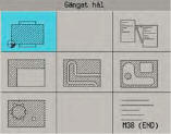
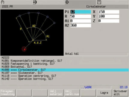
If you want to make a pocket, square och circular amongs others you want to use the IPP
You'll find the IPP if you push the programming
button again.
You need to have the tool set up before using IPP, the functon needs the tool radius to maske the program
A tip for you are that not choose the deep drilling
function in the pocket cycle, Use angel to next, ramping (angel to next…)at
approx 15 degrees. (A3, Drilling 0=NO…)
Choose Storet o go forward thru the menus.
Do you miss anything, walk thru all the menuse and go back and edit later
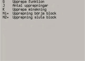
G-function repeat
To repeat part and parts of the program, use G14
Parameters for G14 check the pic below.
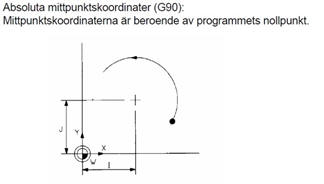
Radie path I,J and K
When you use circular interpolation you use I, J och K, those are Absolute, They get their value from The workpiece Zero point
Drilling
The drill cycle need G78 do defiine the drill points, drill cycle G81 för cutting values and G79 for the drilling itself
N50
G78 P1 X50 Y20 Z0
Define point 1
N55
G78 P2 X50 Y80 Z0
Define point 2
N60 G0 Z10 T1 M6
N65
G81 X1.5 Y1 Z-30 F100 S500 M3
Define cycel
N70
G79 P1 P2
drill at point 1 and 2
Simulating
To make a simulaton of your program, push the program running button two times, choose simulate and cycle run button to execute. You will see the tool path and the coordinate system. You get an wievof how the milling will proceed and avoid any expensive craches. The simulating do not show any tool, just the coodinate point
You can add a whole workpiece to your simulating
G98, G99 och G199 is used to define the workpiece
Check the manual or the programming help for this
I've never succeed with simulate real 3D, the hardware is to weak
DRY RUN
you can make the machine to do a dry run for testing
puroses. Be in Run, choose F-button to reach menu option and choose dry run DRY
RUN in the menu.
Filtransfer
Start the program CDS-on your computer
On hte machine push the diskett-button, choose DATA OUT/IN and Select Device, choose DNC (TCP/IP),click OK. go to the computer ad click reconnect
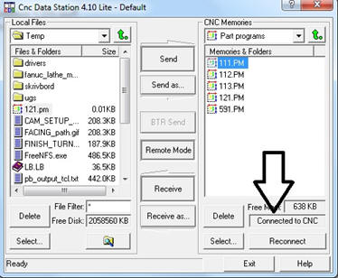
The machine says:
|
Message recived |
|
CDS active on this
CNC
|
Back to the machine.
Choose DATA IN/OUT
=> ID list.
You are now in the program manager in the CNC-control, choose the folder you want to use
from computer to
machine:
Your program need to have the program number on top,
starting with N and the file heed to have the same number and .PM
Reconnect in CDS lite
Send your file
Transferd rows that are illegal get a G301 (faulty code)
From machine to the
computer:
Alarms
The machine is good to throw codes, in the most cases, the explanation is farly easy when using the I-button to read the alarms.
For some reasons the maschne I'm using have a lot of sensor alarm that do not thell you whats wrong
have been:
· chip conveyor whas shut off
· Coolant middle (decanting) punp was shut off
· Filter paper was slacking
Those Alarm, you got to guess whats wrong.
Special functions
M17
Internal wall cleaning (may overflow the machine)
Tool changer cabinet
Be in the
Hand/manual, push I-button. choose I/O, print 789000000 and enter.
A lot off commandos for tool change will appeare in the right menu field, use them carefully
Leave the mode with 0 and enter.
If you feel to pay any amount of money to me use this link paypal link